
6 Typical Plant Engineering Workflows! Summary of 280+ Workshops at 20+ EPCs & O/Os in 19 different countries!
A condensed field synthesis of six typical plant engineering workflows—spanning FEED, process design, instrumentation, automation, and safety—drawn from 15+ years across 20+ EPCs and owner-operators in 19 countries.
A field view of plant engineering
Six company-type workflows drawn from 15+ years across EPCs and owner-operators
In 15+ years of being active in plant engineering, I traveled to 19 countries and got to know amazing plant engineers in 20+ EPCs and owner-operators—and learned about the way they get their jobs done. Here is a condensed summary of all that, put into six typical plant engineering workflows including FEED, process design, instrumentation, process automation, safety design, and more.
Countries: Italy, France, Germany, Austria, Sweden, Norway, UK, UAE, Poland, Netherlands, Switzerland, Denmark, Canada, USA, Singapore, China, India, Malaysia, Indonesia, and South Korea.
The six company types
- Company Type I: Safety I&C of power plants — Europe, Asia
- Company Type II: Automation EPC (oil & gas, pharmaceutical, power) — North America
- Company Type III: Owner-operator engineering (refineries and petrochemicals) — Asia, North America
- Company Type IV: Main automation contractor (coal and water power) — North America
- Company Type V: Subsystem EPC (food and beverage) — Europe
- Company Type VI: Process automation EPC (oil & gas plant design) — Europe
Company Type I: Safety I&C of power plants
Europe and Asia
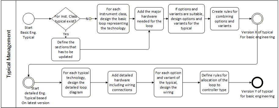
The complete workflow of this company type is divided into two lanes of basic and detailed engineering. The first step in basic engineering is to design the typical technologies that can be reused during the project. The typical-driven workflow will significantly improve the pace of design and ensures the baseline quality of the project.
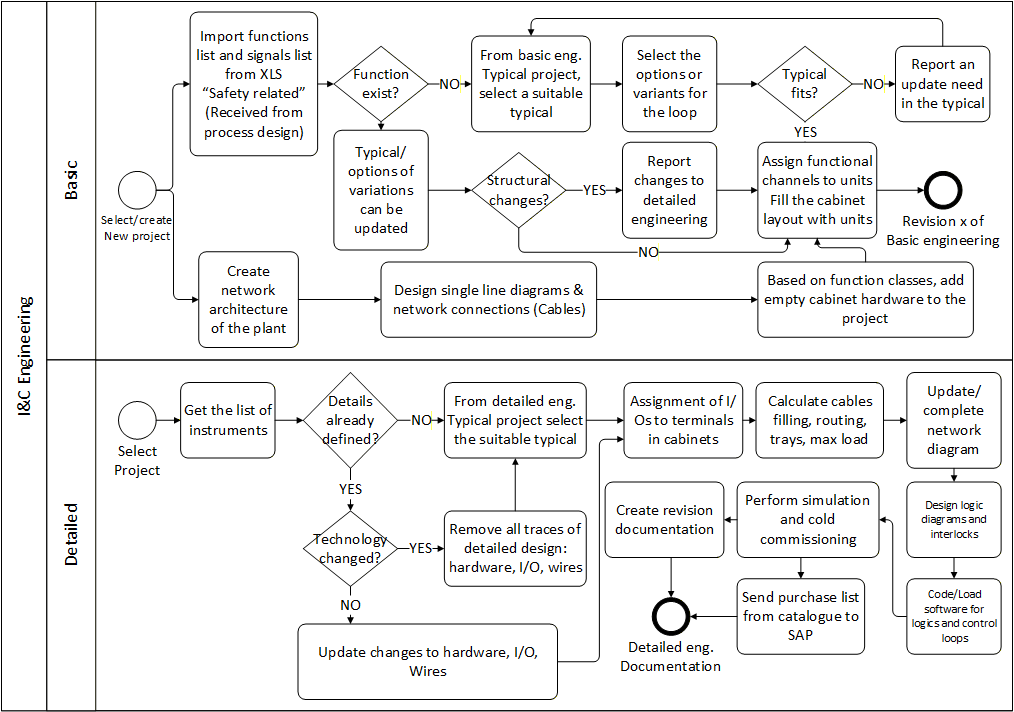
In this workflow, there are two types of typical patterns that should be designed. The first class of typical patterns is the generic technologies that can be used in the basic engineering of each project. These technologies are defined based on the instrument types and vendor, the DCS brand, and the technology which is selected for the project. For each instrument class, a typical loop which is showing the instrument itself, number, and types of connections should be selected. Once the control technology is selected in basic engineering, further steps of designing detailed loop diagrams—including wiring, marshaling, cable routing, I/O allocation, cabinet arrangements, and more—will be performed in the detailed engineering lane.
An I&C EPC section of a main EPC is focused on the safety I&C design of nuclear power generation plants. In this type of company, the main design execution is performed in a combination of different internal and external sectors, and the result of those activities for the complete nuclear power plant design—including process, I&C, and control—will be used as initial project specs of safety design. Safety design procedures will not typically affect the main design of a plant except in rare cases. The main purpose of safety design is to realize mechanisms that will react in cases of emergencies and accidents or work together with routine control systems to avoid undesired situations. Also, hardware that is used in the steady-state control of the plant is preferably not reused for safety purposes due to redundancy policies in case of failures. The general network architecture will be reused as a base layout for placing the junction and control cabinets.
An I&C project execution
The first step in the workflow is receiving requirements and planning engineering tasks. Requirement management should be performed in accordance with the project-specific regulations to guarantee traceability. Utilization of requirement management tools (e.g. Cradle) is recommended. Technical requirements should be identified, analyzed, assigned, and tracked according to project progress and complying with applicable standards such as KTA, IEEE, IEC, RCC-E, or the IEC 61513 standards series (including 60987, 60780, 60880, and related). The project will be defined in distinct phases: basic design and system specification; detailed hardware and software design; configuration management including software/hardware and test; and eventually verification and validation (V&V) of systems and software. At the end of each phase, a phase review shall be carried out to close the phase by checking formal aspects—ensuring planned design and V&V activities were completed and that outputs are consistent with inputs. Verification evaluates whether a product of a phase complies with the inputs to that phase (was it built correctly?). Validation evaluates whether a product meets its intended uses (was the correct product built?).
Overall system specification in basic design
First, the overall system architecture—including equipment, connections, and interfaces—should be specified. Then I&C functions will be assigned to specified equipment. For modernization projects, analysis of existing I&C architecture and plant constraints is a precondition. The next phase is to prepare design concepts such as periodic tests, parametrization, alarm annunciation, decoupling, HMI, interfaces, and security. The outcome of these concepts should be validated by clients. After concepts and functional requirement specifications are consolidated, preliminary data for layout, HVAC, and electrical power supply will be generated. At this phase, analyses such as single failure mode, cybersecurity, response time, spare capacities, and sizing can be performed, and results reviewed against requirements, feasibility, and consistency with existing engineering standards.
Detailed system specification in basic design
At this step, the I&C function specification—which includes logical algorithms, status processing, function diagrams and their assignment to processing units, signals and interfaces, and a library of functional blocks—will be prepared. Thereafter, diagrams will be generated for cabinet specification and arrangement, network and cable specs, analog acquisitions and I/O database, electrical loads per binary outputs, I/O channel allocation and typical hardware diagrams, fuse and breaker definition, and estimation of response times. Next comes HMI specification for service and maintenance and provisions of periodic testing. The last phase of this step is contribution of specifications to boundary systems and validations by customers.
Detailed software and hardware design
After detailed system design in the basic engineering phase, the DCS database will be arranged based on the I&C function spec and library of functional blocks. This includes IT infrastructure (engineering server, service units), IT security measures, and data backup procedures. Each I&C function class should be translated to a DCS method. With such translation definitions, function diagrams can be designed and assigned to a CPU, with cycle time and software parameters configured. Results feed code generation, compilation, and evaluation against software design specs, CPU, and network loads.
Results of approved overall and detailed system specifications will be used for mechanical hardware design: arrangement diagrams, basic wiring and circuit diagrams (naming following KKS or ECS standards), terminal diagrams, cable lists, device diagrams, and jumper diagrams informed by software design data.
Performance analysis
In the final phase of design, deliverables of basic and detailed engineering together with verified and validated software configurations and interfaces will be prepared for analyses such as reliability, accuracy, response time, load, power and heat consumption, and seismic calculations. Results are reviewed and approved by the client in steps depending on the contract, and deliverables are generated in the agreed documentation formats.
Company Type II: Automation EPC
Oil & gas, pharmaceutical, and power plants — North America
As an automation EPC company that executes instrumentation and automation of plants, the first step in the workflow is to receive and reconstruct the project scope specification. Such workflow is based on the flexibility of absorbing documents and data from different brownfield plants in different industries. Documents and lists used in specifying project scope include instrument lists, equipment lists, P&IDs, and process descriptions—received in various formats. This heterogeneity is the natural outcome of the utilization of various CAE tools in various project phases by various disciplines.
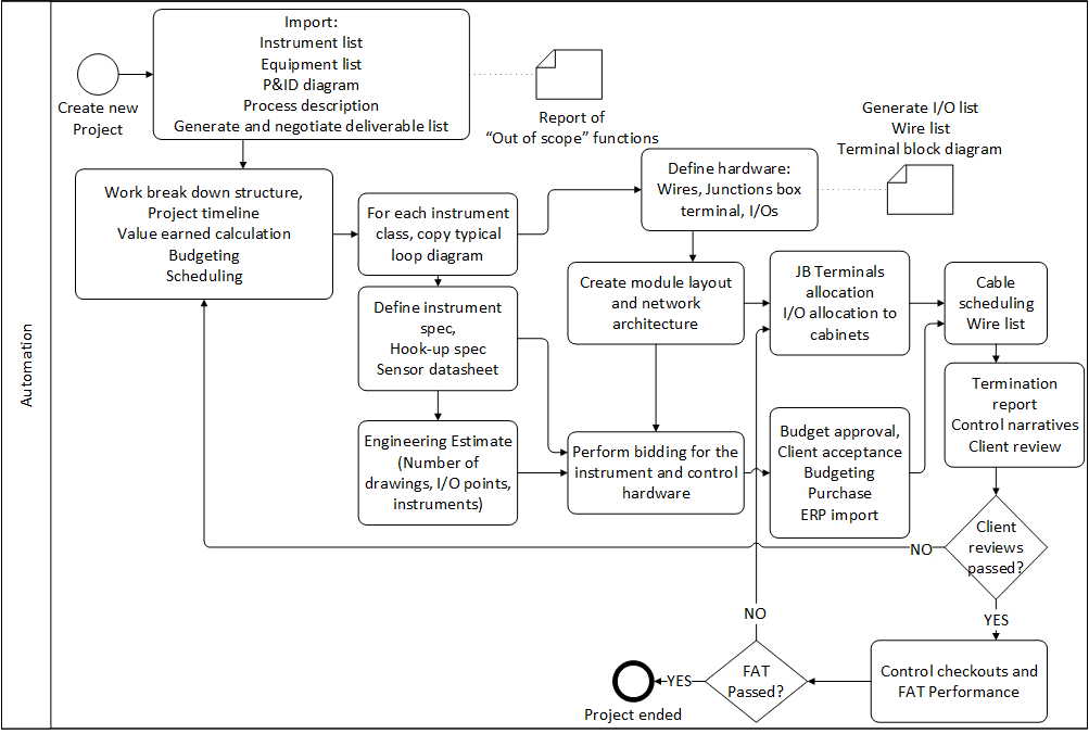
One of the major activities—unique and unpredictable for every project—is data intake, arrangement, unification, and reconstruction of project specification documentation. Only after this step can project scope be fully defined and an execution strategy introduced. It is expensive and time-consuming, and can significantly impact cost and schedule. Nonetheless, it is commercially not feasible to perform it prior to contract finalization. Therefore mid- and small-size automation EPCs are typically at considerable risk of underestimating costs and timeframe—or overestimating and losing the project in tendering. Data mining of previously executed projects and predicting costs based on specification similarities has absorbed considerable attention in this sector.
Engineering estimates are based on countable items such as drawings, I/O points, instruments, and equipment. As important as it is to define what is “in the scope,” it is just as important to define what is “not in the scope,” or removed from the project. Once scope is defined, it is preferred to minimize changes due to distractions that might affect engineering estimates.
After preliminary receipt of project specs and scope definition, the next step is to create the work breakdown structure—enabling phase definition, gateways, ROI calculation, budgeting, and scheduling. Once commercial aspects are approved, instrumentation engineers classify instruments and use typical engineering patterns that document control loops, provide placeholders for wires, cables, and marshaling terminals, populate materials lists, and can generate graphical loop documentation.
Each instrument needs to be specified for procurement tendering, including mechanical mounting (hook-up design). In parallel, hardware estimates for wires, junctions, and terminals can be generated from typicals, and network diagrams showing control module architecture can be designed. Once a detailed overview is achieved, cost can be reviewed with the client to avoid over-engineering. After budget and spec approval, first-version deliverables—wire list, cable schedule, termination reports, and control narratives—are generated and iterated with the client through to as-built and factory acceptance test (FAT).
Company Type III: Owner-operator engineering
Refineries and petrochemical plants — Asia and North America
This type of company typically consists of the following departments: basic process design, process and piping, tendering and procurement, instrumentation, electrical, and automation.
Basic process design is also known as basic engineering or FEED. Process flow diagrams (PFDs) or flow sheets are designed—often not from scratch, because technology principles can be similar across comparable production plants. There are two engineering approaches. The first is “150% design”: a set of PFDs including all feasible options and variations for comparable products is the starting point; engineers extract the flow sheets that satisfy the current project—reducing 150% design to 100% design. This improves cost estimation and scheduling but demands high modularization and standardization, including predefined instrumentation, electrical, and control structures and combination rules for scenarios.
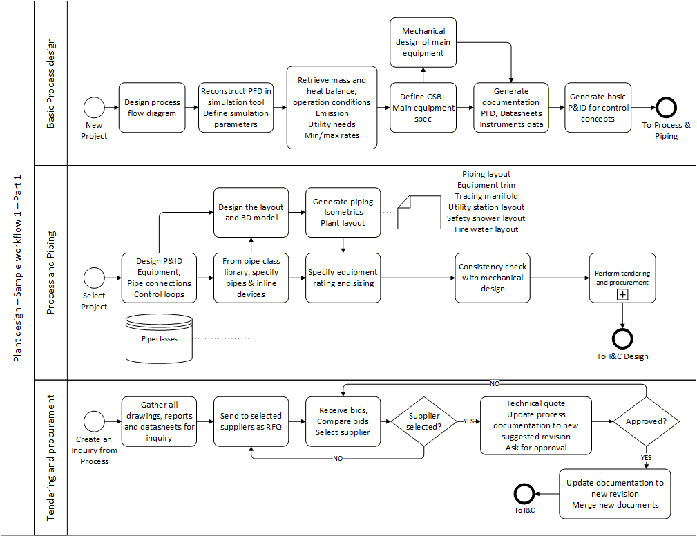
The second approach is to build up the complete flow diagram by merging necessary segments from other comparable projects. After PFDs are specified, calculations such as mass and heat balance, operating conditions, emissions, utility needs, and min/max rates are performed in a process simulation tool such as Aspen Plus. Results complement PFD documentation. Next, production plant boundaries are defined—clarifying utilities (electricity, steam, water, heating and cooling fluids, and more) outside the battery limit.
Once boundaries are specified, preliminary mechanical design of main equipment begins early, because manufacturing needs extensive research and evaluation. Deliverables include PFDs, datasheets, and basic control concepts. Tools commonly used include Aspen Plus, HTRI, and SiNET / FlowMaster.
The process and piping department takes over conceptual design results. The main document is the P&ID—detailed depiction of each device with instruments and controls, plus piping connections and pipe class specifications. Piping engineers follow standards such as ASME and DIN. Once the first P&ID version is generated, 3D designers build plant layout (buildings, civil, equipment, piping) with calculations for stress, weight, wind, heat emission, and hazardous zones. Deliverables include isometrics, plant layouts, equipment location plans, trim drawings, line schedules, and safety-related layouts.
Combined calculation results provide data for equipment rating and sizing. Purchased equipment enters tendering based on generated specifications. Once process delivers its first revision, instrumentation starts from I/O list extraction, P&ID analysis, and process description—running instrument specification (sizing, hook-ups, dimensioning) in parallel with network architecture (panels, cable schedules, interconnections), then loop diagrams from instrument classification and typicals.
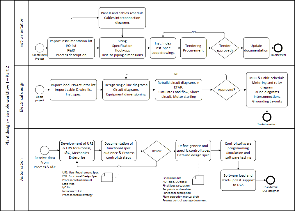
Electrical engineering starts in parallel to I&C from P&ID-derived load and actuator lists, plus cables and wires from I&C deliverables. Single line diagrams show network interconnections; circuit diagrams are selected from libraries and adapted. Consistency is evaluated by recreating circuits in tools such as ETAP for load flow, short circuit, motor starting, voltage drop, and heat capacity simulations.
Automation then begins with URS, FDS, process control manual, step map, I/O list, alarm list, and process control strategy—developed through workshops among process, I&C, and automation engineers. From these, control logic, interlocks, and function charts are created, enabling AO/DO tables, set-points, detailed functional description, plant operation manuals, and HMI design for operators.
Company Type IV: Main automation contractor
Coal and water power plant design — North America
Mainstream projects in this company type are brownfield: the control system of a complete plant or part of it should be revamped. These projects require extensive analysis of already installed processes and infrastructure outside the revamp scope. Sometimes other plant parts are renewed simultaneously by other contractors—increasing complexity and requiring additional communication among owner-operator, MAC, and EPC.
Once P&ID and process description are received, they are manually inspected and analyzed; depending on plant age, location, complexity, and engineer experience, additional field inspection may verify as-built documents. Outcomes include function diagrams, logic interlocks, loads, instruments list, and I/O list. Network architecture is developed and, for partial revamps, merged or made compatible with existing architecture through iterative consistency checks.
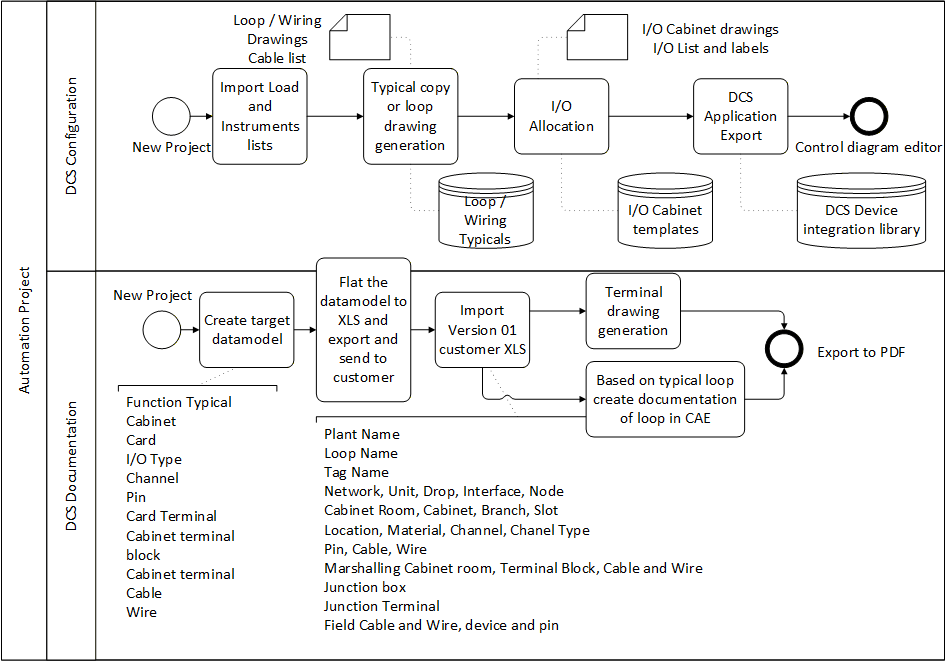
Instruments are classified by functionality and properties; each class follows a pattern providing wiring, junction and marshaling terminals, and I/Os. Cabinets for junctions and marshaling are designed from terminal counts and network interconnections, with placement rules such as optimizing mounting rails, arranging same-voltage terminals, minimizing wiring, and minimizing heat accumulation. I/Os are allocated to channels and cards with visibility of free capacity; calculations for HVAC, firefighting, short circuits, and maintainability are documented and approved before manufacture.
In parallel, control engineers implement logic and HMI with iterative verification and scenario testing. Before steady-state operation, commissioning checks individual equipment, measuring points, and actuators against design documentation—functional tests (drives, fittings, instruments) and systems tests (vessel loading, level/temperature/pressure control, compressor start/shutdown, exchangers, reactors).
Cold commissioning is a minimal-risk test run—often with ambient water and no heating in liquid plants—activating local controls first, then the main program, and tuning PID and timing elements. Warm commissioning tests and optimizes operation with heat supply or removal and process material under reaction heat.
Company Type V: Subsystem EPC
Food and beverage — Europe
Subsystem engineering companies deal with limited product-line variations they can manufacture as complete subsystems—boilers, incinerators, waste treatment, solvent recycle, water treatment, and similar. Detailed engineering is a small portion of the workflow; focus is mostly on tendering/quoting and basic process design, using pre-engineered modules. P&IDs represent relations between systems that are sometimes treated as black boxes. The workflow optimizes two aspects: agile, accurate technical quotes; and plant documentation by integrating predefined, verified modules with minimal later manual change.
In a sample company, of about six quotation requests per year on average, only one becomes a confirmed full-execution project. The workflow must trade off minimal engineering hours in quote generation against maximal agility, accuracy, and reliability in the quotation phase.
Contract management starts with collecting project requirements—typically driven by a sales engineer from tendering meetings. Documents arrive in Excel, PDF, Word, or even scans. The most important are interconnections to battery limits (process and utility inputs/outputs across operating conditions) and layout (available plant location for the subsystem).
Specs are distributed to process and I&C, engineering layout, and utility design. Teams cooperate on price estimates and subsystem description; accuracy depends on engineer experience and availability of verified modules. Deliverables are stored in SAP and sent as the RFQ response.
Once a proposal wins, the same specification documents typically guide further design. Technology selection depends on expected quality and quantity of outcome, available utilities, and—for waste, incineration, or water treatment—environmental regulations. P&IDs are built from verified modules; if none fit, a new module is designed and verified as a parallel external sub-project. Main design then covers process and mechanical fitting, electrical loops and circuits, 3D layout, load and utility calculation, and control software and HMI—mostly adapting modules and synchronizing merged documentation.
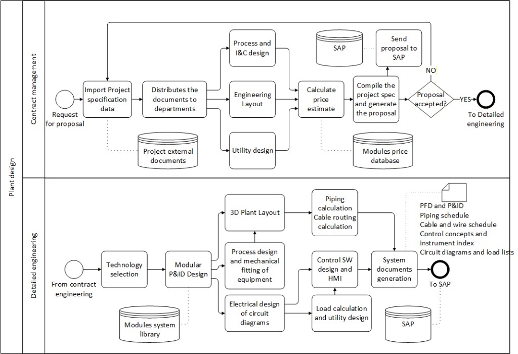
Collection of generated documents is sent to SAP as the first design version for review by the plant owner or EPC.
Company Type VI: Process automation EPC
Oil & gas plant design — Europe
In this workflow, three disciplines are involved: project planning, basic engineering, and detailed engineering. In planning, the contract and requirement list are received from sales and analyzed. Suitable standards and project structure are planned—including review timelines, checkpoints, and deliverables. If safety systems are included, their specifications are received and analyzed, and an execution strategy is established for engineering and test steps.
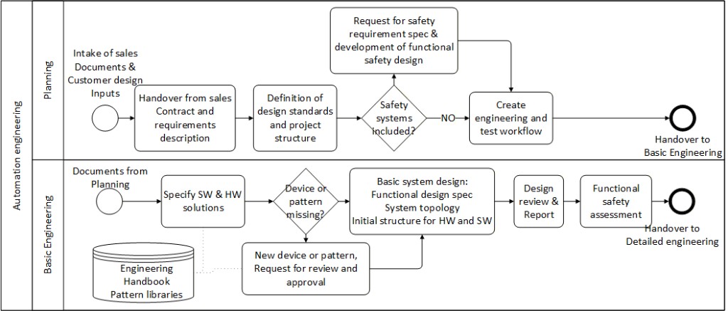
The first design engineering step is to identify software and hardware automation solutions from the engineering handbook and pattern libraries. Missing solutions can be requested, then designed and verified before use. Based on selected solutions, a functional design document—the backbone of the project—is drafted and updated iteratively. In parallel, system topology and structure diagrams are designed, reviewed by clients, and verified by process and P&ID designers. Safety functions receive an extra assessment step due to maximal accuracy requirements.
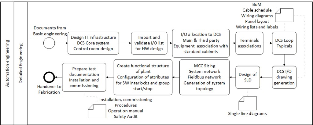
In detailed engineering, IT infrastructure and control room arrangement are designed from topology and structure diagrams. The client I/O list drives hardware ordering—often using standard control cabinets with predefined mounting rails and filling rules. I/Os are allocated to DCS cabinets with associations to main and third-party equipment. Marshaling and junction terminals are arranged; with instruments, terminals, I/O, and DCS cabinets in place, typical loop libraries drive wiring and cabling. Deliverables include BoM, cable schedule, wiring diagrams, panel layouts, wiring lists and labels, DCS I/O drawings, and SLDs. System network, Fieldbus network, and topology details follow; finally, functional plant structure is built in the controller developer interface with interlocks and group start/stop attributes.
For the test phase, installation and commissioning procedures, handbooks, operation manuals, and safety audits are used. Procedures across operating modes are verified against the functional description; inconsistencies drive corrections and manual updates, and in certain change cases safety protocols and audits are revised and verified again.